We load the ABEM Terrameter and a set of heavy-duty stainless steel electrodes into the van before heading out through the York ring road. The York Vale, with its thick lacustrine clays and hidden gypsum lenses, presents a unique challenge for conventional borehole investigation. Vertical Electrical Sounding cuts through that ambiguity. By injecting a controlled current into the ground and measuring the potential difference across expanding electrode spreads, we map subsurface resistivity contrasts down to 30 or 40 metres. In a city where the River Ouse and River Foss have been reshaping the floodplain for millennia, knowing whether you are sitting on stiff glacial till or waterlogged alluvium before you break ground saves weeks of re-design. When the survey line runs near the city walls, we often pair the resistivity data with a seismic refraction profile to tie geophysical layers to actual velocity horizons, giving the structural engineer a clearer picture of bedrock depth.
A single resistivity sounding across the York moraine can distinguish dense lodgement till from soft glaciolacustrine clay better than three window samples spaced ten metres apart.
Process and scope
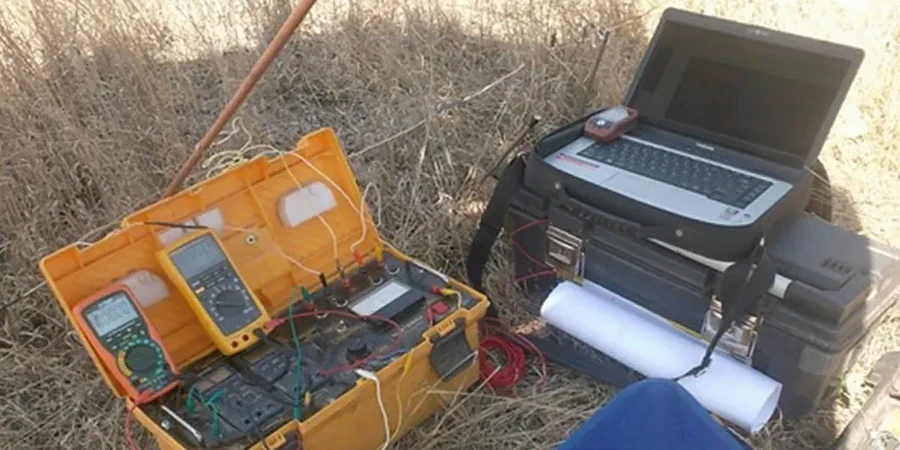
Local ground factors
Compare a site near Bishopthorpe on the floodplain with one up on Tadcaster Road, and you are dealing with two completely different electrical signatures. Down by the Ouse, saturated alluvium and sand lenses give resistivity values below 20 ohm-metres, masking the true depth to bedrock and making it easy to underestimate pile lengths. Up on the moraine, dry gravels can spike above 200 ohm-metres, creating a high-contact-resistance problem that fools a lazy operator into thinking they have hit sandstone at half the real depth. The gypsum beds in the Mercia Mudstone, particularly around the Fulford area, introduce another hazard: dissolution features and small sinkholes that show up as dramatic resistivity lows. Ignoring these anomalies during a desk study and relying solely on rotary boreholes means you might miss a three-metre void between two perfectly competent cores.
Relevant standards
BS 5930:2015+A1:2020 – Code of practice for ground investigations, Eurocode 7: BS EN 1997-2:2007 – Ground investigation and testing, BS EN ISO 22475-1:2021 – Geotechnical investigation and testing, BRE Digest 472 – Working platforms for tracked plant
Other technical services
Vertical Electrical Sounding (VES)
Deep 1D resistivity profiling using Schlumberger array geometry to map layer thicknesses and identify the bedrock interface beneath glacial drift and alluvium.
2D Electrical Resistivity Tomography (ERT)
Multi-electrode profiling along linear transects for pipeline routes, embankment investigations, and detecting lateral variations in the Sherwood Sandstone aquifer.
Karst and dissolution feature mapping
Targeted resistivity grids over the Mercia Mudstone gypsum beds to delineate potential sinkhole zones prior to residential or commercial development.
Typical parameters
Quick answers
What does a VES survey in York typically cost?
For a standard campaign of four to six vertical electrical soundings with Schlumberger array and full interpretation, rates generally fall between £480 and £760 per day depending on access conditions and the total line-kilometres. Complex urban sites around the city centre, where we must avoid buried utilities and negotiate pedestrian traffic, sit at the upper end of the range.
How does VES differ from a 2D resistivity imaging survey?
VES gives you a one-dimensional layered model directly beneath a single point, making it ideal for deep bedrock mapping at discrete locations. A 2D ERT line uses a fixed multi-electrode cable to produce a continuous cross-section along a profile, which is better for tracking lateral changes along a proposed road alignment or beneath an existing embankment.
Can resistivity surveys work in the waterlogged ground near the River Ouse?
Yes, and in fact the saturated conditions often improve the signal-to-noise ratio because pore water reduces contact resistance. The key is using a longer current injection time and automatic stacking to suppress the cultural noise from the York grid. We always calibrate the inversion model against at least one borehole or trial pit log to constrain the interpretation of the low-resistivity clay and silt layers.