Across York, the River Ouse and its tributaries have left a legacy of soft silts, peats, and loose alluvial sands that make conventional shallow foundations unworkable on many brownfield sites. We routinely encounter 2 to 5 metres of very soft, compressible material overlying the Sherwood Sandstone or Mercia Mudstone, creating exactly the conditions where vibrocompaction alone cannot provide the required stiffness. Stone column design here demands a granular understanding of how these layered deposits consolidate under load. Our approach starts with a detailed ground model built from CPT logs and borehole data, then moves directly to unit cell settlement analysis and column spacing calculations under the framework of BS EN 1997-1:2004. The goal is practical: deliver a treated ground platform with a modulus of deformation that allows pad footings or a mat foundation to perform within Serviceability Limit State criteria, without over-designing the grid and blowing the construction budget on stone that isn't needed.
In York's alluvial corridors, stone column spacing is driven by settlement tolerance, not bearing capacity — get the modulus right and the rest follows.
Process and scope
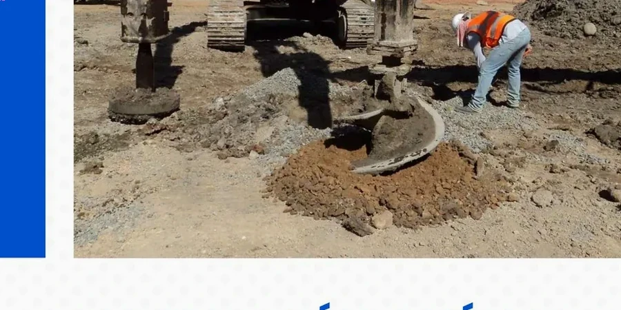
Local ground factors
York's medieval core and Victorian expansion pushed development onto the floodplain, where centuries of archaeological deposits and industrial fill sit atop natural soft alluvium. The risk isn't just settlement magnitude — it's differential movement between column-supported areas and adjacent ground. We've seen a warehouse slab rotate 40 mm across 8 metres because the transition zone between treated and untreated ground wasn't properly detailed. Column design in these conditions must include a thorough analysis of lateral extent: where does the improved zone stop, and how does that interface behave under service loads? The groundwater regime adds another layer of complexity. The Ouse's level fluctuates seasonally by over 2 metres, and column installation through saturated silts can trigger temporary pore pressure increases that reduce the undrained strength during construction. Our design reports always specify a monitoring protocol for adjacent structures within the zone of influence, typically extending 2.5 times the column length from the perimeter of the treatment area.
Relevant standards
BS EN 1997-1:2004 (Eurocode 7 — Geotechnical design, General rules), BS EN 1997-2:2007 (Eurocode 7 — Ground investigation and testing), BS EN 14731:2005 (Execution of special geotechnical works — Ground treatment by deep vibration), BS EN 13242:2002+A1:2007 (Aggregates for unbound and hydraulically bound materials), BS 5930:2015 (Code of practice for ground investigations)
Other technical services
Stone column design package
Full analytical and numerical settlement analysis using Priebe or finite element methods. Includes column length, diameter, grid spacing, aggregate specification, and installation sequence drawings. Delivered with a Design Assumptions Schedule aligned to BS EN 1997 Design Approach 1.
Performance verification testing
On-site supervision of trial column installation and zone load testing to confirm modulus of deformation. We correlate plate test data with CPT profiles to validate the design assumptions and recommend grid adjustments before the main production phase.
Typical parameters
Quick answers
What ground conditions in York typically require stone columns instead of standard foundations?
Soft alluvial clays and silts with undrained shear strength below 40 kPa, peat layers, or loose saturated sands where vibrocompaction alone cannot achieve the required bearing capacity. Much of the city centre and areas near the Ouse and Foss fall into this category. Stone columns become viable when the treatment depth needed is between 3 and 8 metres and the natural ground has sufficient lateral confinement to prevent column bulging failure.
How do you verify that the installed columns meet the design assumptions?
We specify a trial phase with three to five columns installed at the design spacing, followed by a zone load test or individual plate load test. The load-settlement curve is measured directly and compared to the predicted response from the design model. We also run post-installation CPTs through the column centre and the inter-column soil to confirm densification and column continuity. Only after passing these checks does full production proceed.
What is the typical cost range for stone column design and verification in York?
For a typical commercial or industrial project in the York area, the design package and site verification testing generally falls between £1,000 and £4,000, depending on the treated area, number of trial columns, and complexity of the ground model. A detailed proposal is provided after reviewing the available ground investigation data.
Can stone columns be installed close to existing structures along York's narrow medieval streets?
Yes, but with careful vibration monitoring. The dry bottom-feed method generates lower lateral vibration than top-feed rigs and is preferred within 5 metres of sensitive buildings. We set vibration trigger levels based on BS 7385-2 and require continuous monitoring with geophones on adjacent walls. The monitoring data feeds back into the installation sequence to adjust hammer energy if needed.
What settlement performance can we expect from a properly designed stone column scheme?
Total settlement is typically reduced by a factor of 2 to 4 compared to untreated ground, and differential settlement across the improved area is generally kept below 1:500. The exact performance depends on the area replacement ratio, column length, and the compressibility profile of the underlying soils. We provide settlement predictions at design stage and confirm them through the trial zone testing programme.